How to activate, commission and use Modbus TCP server-slave functionality
General information
Fidelix FX2030, FX2030A, FX-SPIDER, FX3000-C and the new FX-SPIDER 40/10 substation CPUs may be updated with new software version 12.30.06 which supports a Modbus TCP/IP server functionality. It allows FX-series substation to respond to remote Modbus TCP senders like SCADA systems or AHU units and transfer own registers over the LAN IP networks.
 NOTE! MODBUS SERVER has certain limitations in register and communication settings. Read carefully before starting Modbus network planning.
COMMISIONING
FX CPU software requirements
Check if your CPU has internal Fidelix software version supporting Modbus Server feature:
12.20.34 and 12.30.06 are available at 10.10.2020
Check the latest software versions and drivers here:
https://info.fidelix.fi/fi/knowledge/lataukset
http://support.fidelix.fi/ProgramVersions.aspx

NOTE! You shall sign in to the service in order to ACTIVATe MODBUS SERVER features. Apply for the login and password at www.support.fidelix.fi.
Activating Modbus server features
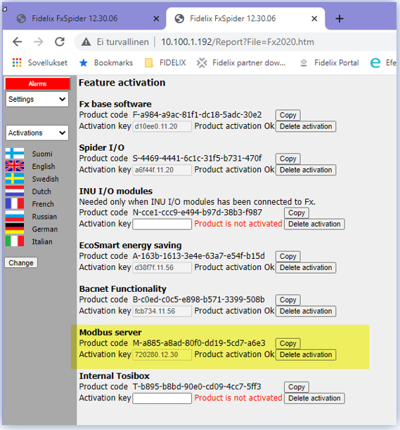
If at your FX-series CPU is no product activation for the Modbus Server feature, Settings -> Activations page will look like following:

Already activated Modbus Server feature:
The Modbus Server features must be activated from the Fidelix Product Activation page :
http://support.fidelix.fi/ActivationForm.aspx
https://activations.fidelix.com
NOTE! You shall sign in to the service in order to ACTIVATe MODBUS SERVER features. Apply for the login and password at www.support.fidelix.fi.

New activations page: https://activations.fidelix.com/Activations

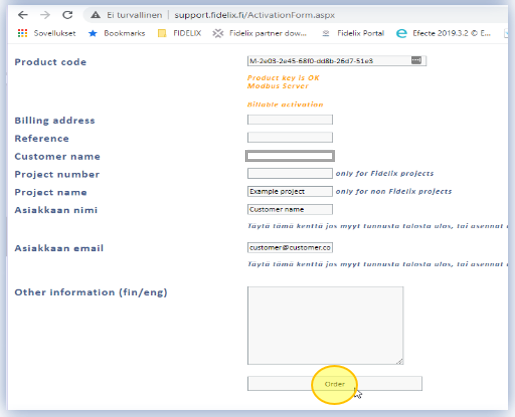
Enter the product code from the Modbus Server component of “Activation” Settings page, as well as project / device related information, then press the "ORDER" button :
NOTE! The activation may be subject of billing.
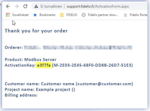
The following page displays the “ActivationKey” alphanumeric string to be entered into the FX-3000-C field. Same notification and activation key will be emailed to you.
After entering the activation key in the FX substation interface, you should press the "Change" button :
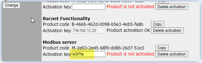

 When the text "PRODUCT ACTIVATION OK" appears, the Modbus server features are activated.
Hardware setup
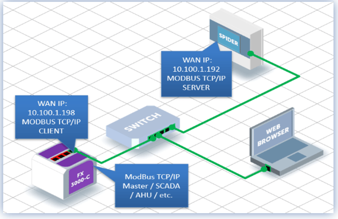
Modbus Server functionality will be tested on following setup:
- Modbus server -> FX-2030A SPIDER CPU
- Modbus client -> FX-3000-C CPU
May be any of Modbus TCP/IP “Master/Client”
device/software like SCADA, AHU etc.
Web-browser on the same LAN network PC
NOTE! Check that all devices are in the same LAN ip address range
ModBus register mapping
OpenPCS Driver update
Server registers mapping shall be done in IEC code. OpenPCS programming environment (alternatively FX-Editor and its application ST-Edit) shall be used to program corresponding register numbers, their variable data types, and value sources.
IMPORTANT NOTE! Check that Infoteam OpenPCS drivers are up to date!
Latest driver versions are available from: http://support.fidelix.fi/ProgramVersions.aspx

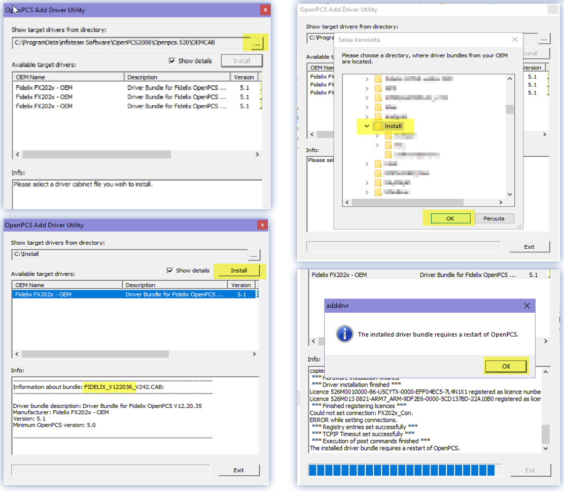
Download and unpack fidelix_V122036_V242.cab file to your PC.
Update the driver pack as following:
- Start OpenPSC, select Extras -> Tools -> Driver Install
- Click on button
 and select folder with unpacked cab file
 - Check if the bundle version is correct: 122036
Click “Install” button, wait for finish and restart OpenPCS manually

Modbus Server register functions
Note! Max value for INT variable in IEC compiler is 32767 and bigger values must be - written in hexadecimal format (e.g 32769 equals 16#8001) - or given like this: WORD_TO_INT(32769). Values bigger than 32767 are displayed as negative values in OpenPCS watch window. Hexadecimal display format may be selected from menu "View-Number format".
Modbus register writing
Function SetModbusIntF sets register value and returns INT value 1 or 0
Parameters:
Address (INT) Register number 0 .. 65535
Value (INT) Register value
Function SetModbusWordF sets register value and returns INT value 1 or 0
Parameters:
Address (INT) Register number 0 .. 65535
Value (WORD) Register value
Function SetModbusDIntF sets values of two subsequent registers and returns INT value 1 or 0
Parameters:
Address (INT) Register number 0 .. 65534
Value (DINT) Register value
Highest 16 bits are saved at Address and 16 lowest bits at Address+1
Function SetModbusDWordF sets values of two subsequent registers and returns INT value 1 or 0
Parameters:
Address (INT) Register number 0 .. 65534
Value (DWORD) Register value
Highest 16 bits are saved at Address and 16 lowest bits at Address+1
Function SetModbusDWordF sets values of two subsequent registers and returns INT value 1 or 0
Parameters:
Address (INT) Register number 0 .. 65534
Value (DWORD) Register value
Highest 16 bits are saved at Address and 16 lowest bits at Address+1
Function SetModbusRealF sets values of two subsequent registers and returns INT value 1 or 0
Parameters:
Address (INT) Register number 0 .. 65534
Value (REAL) Register value
Highest 16 bits are save at Address and 16 lowest bits at Address+1
Multiplier (INT) Multiplier used for conversion (0 = no conversion)
If Multiplier is bigger than zero then REAL value is saved to registers as DINT so that first REAL value is multiplied by Multiplier and then it is converted to DINT.
Example: SetModbusRealF(Address:=10, Value:=345.67, Multiplier:=100) saves DINT value 34567
If you want to save REAL value without conversion to DINT then set Multiplier:=0. Format used at save is then IEEE Standard for Floating-Point Arithmetic (IEEE 754)
Modbus register reading
Function GetModbusIntF returns register value as INT
Parameters
Address (INT) Register number 0 .. 65535
IEC complier interpretes values over 32767 as negative. If you want to use such value as unsigned do this.
Read first value to WORD variable using GetModbusWordF and assign it to DINT variable using WORD_TO_DINT().
Function GetModbusWordF returns register value as WORD
Parameters
Address (INT) Register number 0 .. 65535
Function GetModbusDIntF returns values of two subsequent registers as DINT
Parameters
Address (INT) Register number 0 .. 65534
Function GetModbusDWordF returns values of two subsequent registers as DWORD
Parameters
Address (INT) Register number 0 .. 65534
Function GetModbusRealF returns values of two subsequent registers as REAL
Parameters
Address (INT) Register number 0 .. 65534
Multiplier (INT) Multiplier used for conversion (0 = no conversion
If Multiplier is bigger than zero then function returns REAL value so that DINT in registers is first converted to REAL and then it is divided by Multiplier.
Example: GetModbusRealF(Address:=10, Multiplier:=100) returns value 345.67 if registers are holding DINT value 34567
If you want to read REAL value without conversion from DINT then set Multiplier:=0. Registers must now hold REAL value in format IEEE Standard for Floating-Point Arithmetic (IEEE 754)
Modbus Server program examples
Modbus register writing at the Server side
VAR
iResult :INT;
END_VAR
PROGRAM

iResult := SetModbusIntF(Address := 1, Value:= 123);
(* Sets Holding register #1 with value 123 *)

iResult := SetModbusWordF(Address := 2, Value:= INT_TO_WORD(2345));
(* Sets Holding register #2 with value 2345 *)

iResult := SetModbusDIntF(Address := 3, Value:= 345678);
(* Sets Holding registers #3 and #4 with double INT value 345 678 (Hex 0x0005 and 0x464E) *)

iResult := SetModbusDWordF(Address := 5, Value:= DINT_TO_DWORD(1234567890));
(* Sets Holding registers #5 and #6 with double INT value 1 234 567 890 (Hex 0x4996 and 0x02D2) *)

iResult := SetModbusRealF(Address := 7, Value:= 67.89, Multiplier:=10);
(* Sets Holding registers #7 and #8 with value 345 678 (Hex 0x0005 and 0x464E) *)

iResult := SetModbusRealF(Address := 9, Value:= 11.12, Multiplier:=0);
(* Sets Holding registers #9 and #10 with value 345 678 (Hex 0x0005 and 0x464E) *)

END_PROGRAM
When OpenPCS (of FX-Editor and ST-Edit) will upload and start the IEC program, registers 1..10 will be available for reading and writing from Modbus Client / Slave.
Modbus register reading at the server side
VAR
iResult : INT;
rResult : REAL;
wResult : WORD;
dwResult: DWORD;
dintResult : DINT;
END_VAR
PROGRAM

iResult := GetModbusIntF (Address := 1);
(* Returns INT value of Holding register #1 *)

wResult := GetModbusWordF (Address := 2);
(* Returns WORD value of Holding register #2 *)

dintResult := GetModbusDIntF (Address := 3);
(* Returns DINT value of Holding registers #3 and #4 *)

dwResult := GetModbusDWordF (Address := 5);
(* Returns DWORD value of Holding registers #5 and #6 *)

rResult := GetModbusRealF(Address:=9, Multiplier:=100);
(* Returns REAL value divided by 100 of Holding registers #9 and #10 previously set with DINT value*)

END_PROGRAM
When OpenPCS (of FX-Editor and ST-Edit) will upload and start the IEC program, registers 1..10 will be available for reading and writing from Modbus Client / Slave.
Modbus register mapping
Modbus register mapping at the client side
Modbus TPC client “Master” configuration for SCADA, AHU, and other devices to be done according to manufacturer’s rules.
In the test setup we are using Fidelix FX-Series substation (IP 10.100.1.198) as Modbus TCP Client (MASTER). Configuration of Modbus registers at the “Master” side shall be done at menu User Mode -> Programming -> Modbus Devices
New Modbus mapping may contain 1 or more Holding Registers connected to “Server” device IP (10.100.1.192) on IP Port 502.
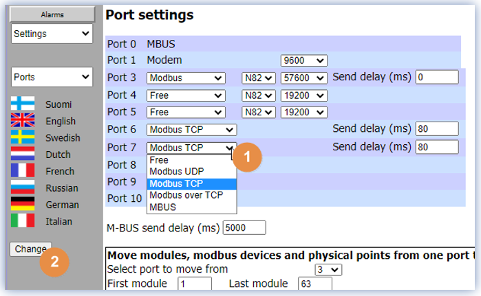
Configure available Serial port as “Modbus TCP”
User Mode -> Settings -> Ports -->
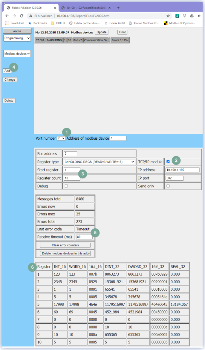
At the menu User Mode -> Programming -> Modbus Devices
Set port number and Modbus device address.
Set “TCP/IP module” and IP address of Server.
Set starting register number and number of subsequently reading registers
Add Modbus device
Make sure that communication is established (“Communication OK”). “Messages total” indicates number of accepted Modbus messages from Modbus Server.
You may need to adjust sending and receive delays if error number is growing.
Valid Modbus register types (Modbus function) are:
- READ_MULTIPLE_REGISTERS (Function 3) for reading group of registers
- WRITE_MULTIPLE_REGISTERS (Function 16) for writing group of registers
- WRITE_SINGLE_REGISTER (Function 6) for writing single register
When Modbus Server registers are written with OpenPCS IEC functions, their values will be displayed in the table at the bottom of the screen.
Different data types allow user to check if values are correct.
By default, the server listens to IP port 502 and it may be changed in firewall settings. User Mode -> Settings -> Firewall
Modbus register reading at the Server side (MODBUS SLAVE)
When above mentioned OpenPCS IEC reading program is running on a Modbus Server FX-substation, it returns Holding register values if Client (Modbus Master) sets those. Values may be used as e.g. setpoints, control signals, alarms etc.