
Fidelix Tech Oy
Myllynkivenkuja 1
01620 Vantaa
Finland
+358 9 250 1288
General safety instructions
Note
The system time default is 15 minutes. If the system is unoccupied over 15 minutes the system will log the user out for the safety reasons. The default time can be changed on the Settings view.
General description
On the building automation there can be either physical I/O acess points (input/output) or program points. Controller has moduls which corresbond to the I/O points. Programmatic set points are fictitious/fixed/imaginary and they carry out different kind of actions.
After logging in the user will see the dashboard. On the Dashboard the user can:
- choose cards to the dashboard
- delete cards on the dashboard (all at once)
- use default dashboard.
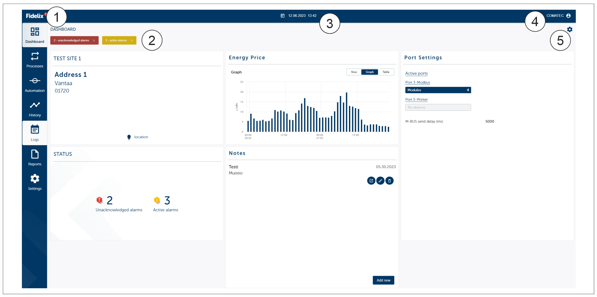
|
1 |
Alarms info number beside the Fidelix logo |
|
2 |
Alarms |
|
3 |
Calendar (time and date) |
|
4 |
Log out and language settings |
|
5 |
Dashboard settings |
Note
Tap the Dashboard tab to go back to the Dashboard.
Processes
On the Processes tab the user can see Process settings and process pictures.
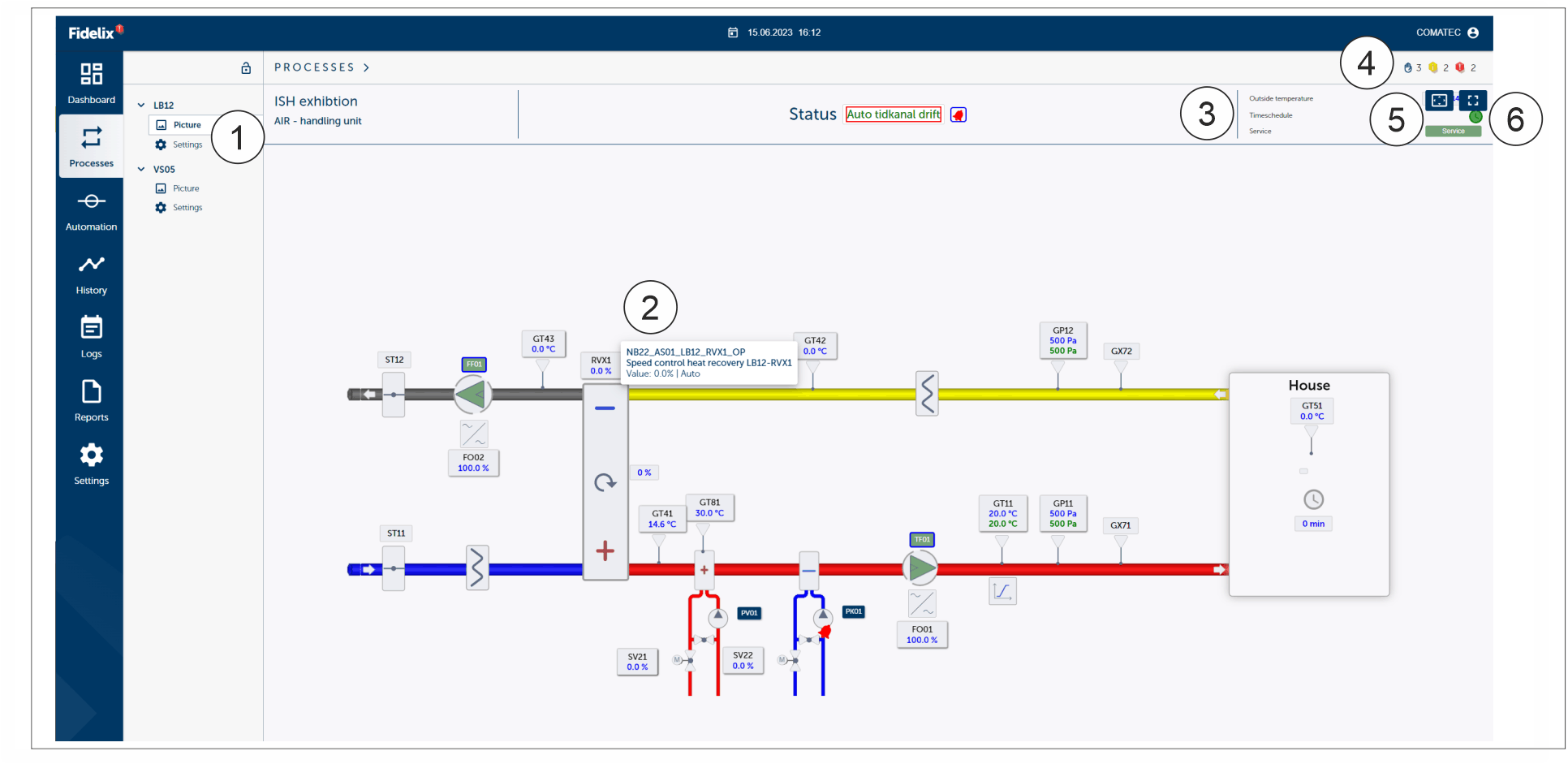
|
1 |
Point information, picture and settings |
|
2 |
Process details |
|
3 |
More information |
|
4 |
Unakcknowledge alarm |
|
5 |
Centering |
|
6 |
Small or big picture |
Tapping the process point the user get’s more information and details from the point details. User can:
- check the point details
- correct the point details (all users have no rights to correct the point details)
- edit the point details (all users have no rights to edit the point details)
- see the trend chart
State of point:
Every point is allways some of these state:
- Auto (1): Automatic values. The visible value is the real value of the point (normal state).
- Program (2): PCL program has calculated the value for the point (normal state)
- Manual (3): The point is on the manual steering and the user gives the values.
The point states has dominant order (1 strongest, 3 weakest):
- Manual state is the most dominant state.
- Program state can overwrite the Auto state.
- Auto state is the weakest state but there are some exceptions where the Program state can be more dominant than the Manual state.
Text and box colour on the process picture:

- Red. Alarm state (1). The reason for the alarm state can be:
- Blue. Manual state (2). Manual state overrides all the program actions.
Note
The action name is grey if the action is not activated or the user has no rights to do the action.
Automation
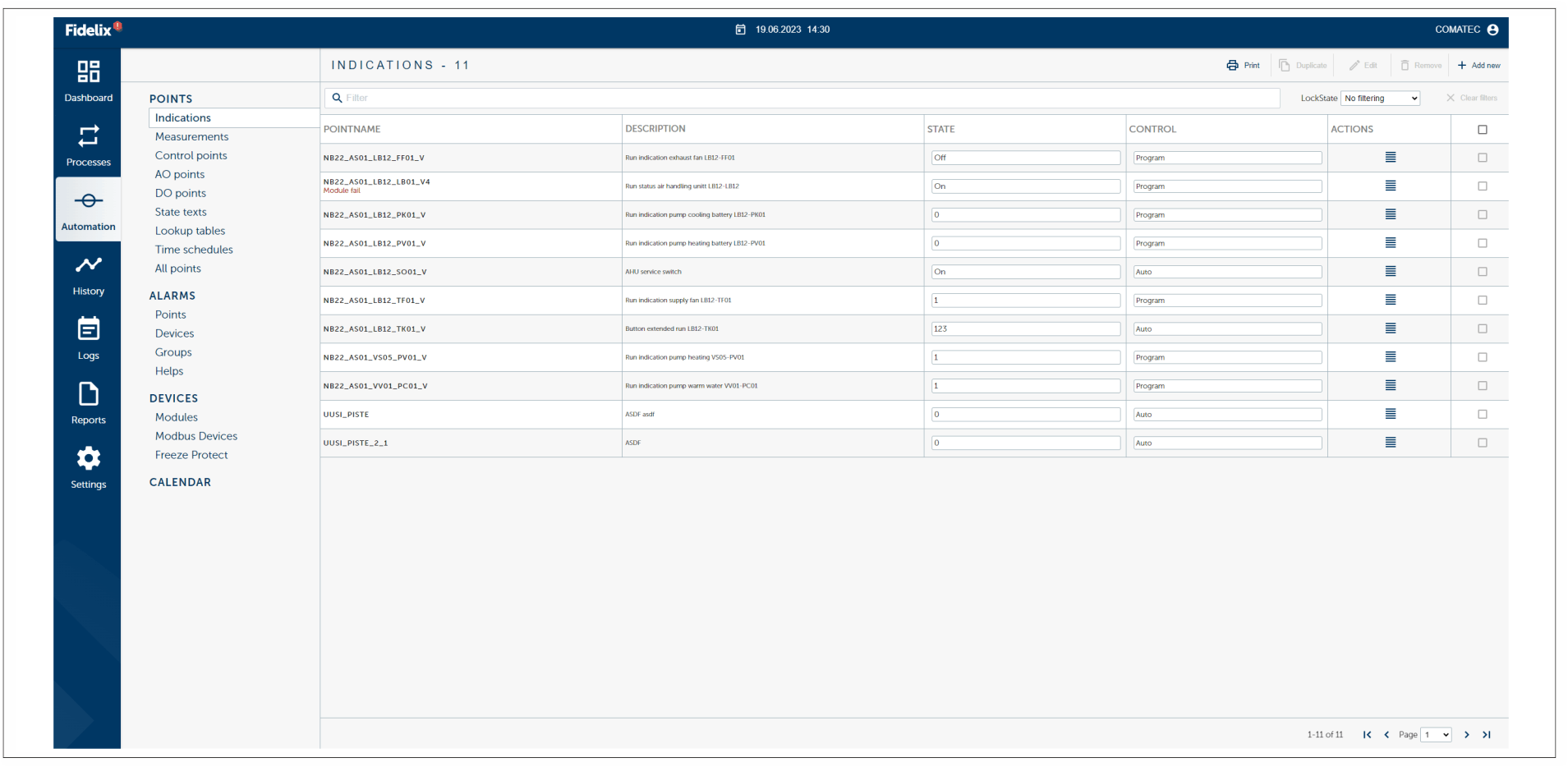
On the Automation tab the user can see
- Points
- Alarms
- Devices
- Calendar information.
Note
For more detailed information see the Fidelix programming manual.
Points
All relevant functions and features in a Fidelix BMS are linked to points. The Fidelix BMS supports a variety of point types such as physical points, programmable points, limits, set points etc.
Points tab offers more for all different point types linked to the Fidelix BMS.
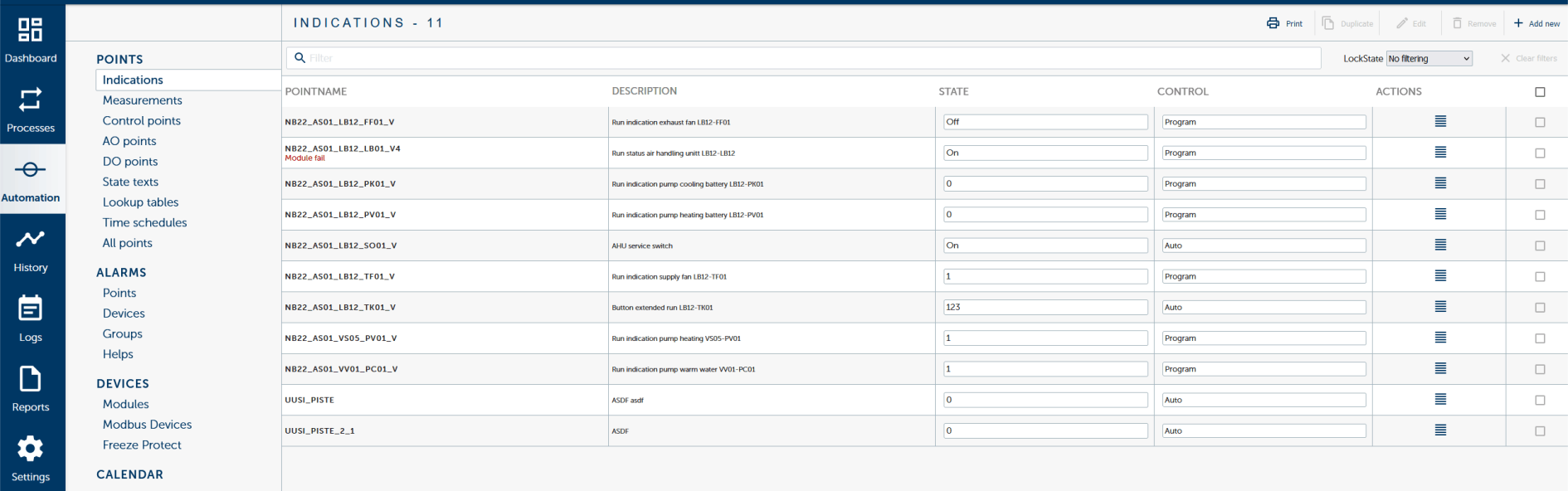
Indications (DI, Digital Input)
Indications are digital input points which can be physical or programmable. The point typeis a state indication.
Point type ‘Indication’ can be used for example for- supervising a state of input in a digital input module- displaying a state controlled by IEC program- displaying a value controlled manually
Measurements (AI, Analog Input)
Measurements are analogical input points which can be physical or programmable. Thispoint type is for measurements and other analogical values.
Point type ‘Measurement’ can be used for example for- measuring value of sensor connected to AI module- counting impulses from contact in DI module - displaying value controlled by IEC program- displaying value controlled manually- running time counting
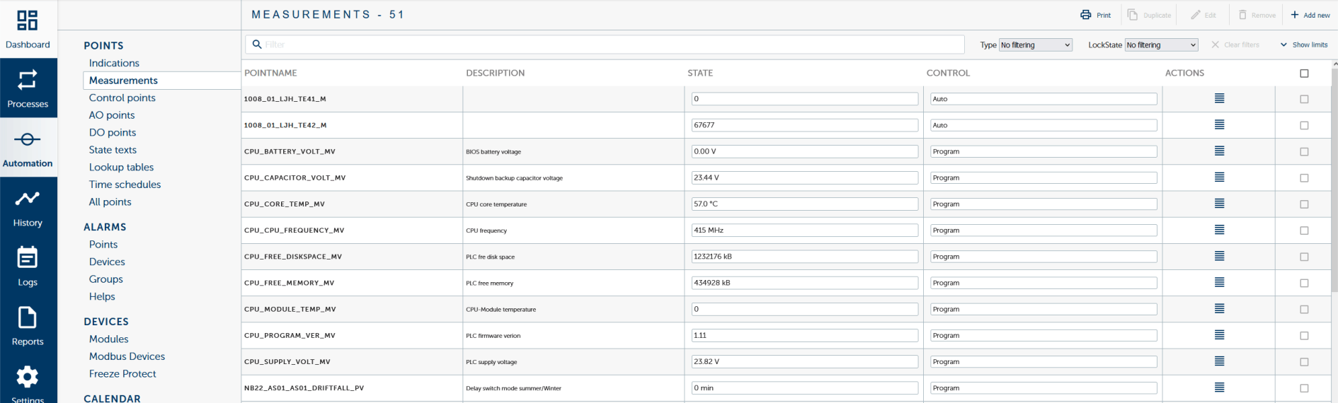
Choose Automation - Measurements to open the measurements view.
Control points
Control point operates always internally in range 0..100%. Control points are a more complex point type. It can be used from simple single stage control (e.g. domestic water) to a 6 stage air handling unit.
AO points (Analog output point)
AO points are analogical output points which can steer the physical devices to different positions (0-10 V). For example valve motors, frequency converters etc.
Select analog output point. If defined, value of this point will be set according to stage value.If stage is controlling device that needs more limiting functions than available in control point do not define AO point here. Stage value can be read into IEC program where you can make complex operations to stage value before setting valueto AO point.
Point type ‘AO’ can be used for
- Controlling actuator connected to AO module with 0..10VDC signal
- Displaying value controlled by IEC program
- Displaying value controlled manually
DO points (Digital output point)
Control points are digital outputpoints which steers the physical devices on/off. With control points the user can steer for example lightning, pumps or frequency controllers.
Point type ‘DO’ can be used for:
- Controlling state of relay in DO module
- Displaying state controlled by IEC program.
- Displaying state controlled manually
State texts
State text is select state textgroup for displayingpoint state in textmode states insteadof numbers.
State text shows the numeric value as text for user.
Lookup tables (conversion table)
Point type Conversion table can be used for:
- Converting raw measurement value from AI module to engineering units
- Creating compensation table for set value of control point
- Calculating any nonlinear value in IEC program
Time schedules
Select time schedule that gives state of DO point if itis in automatic mode.
Point type ‘Time schedule’ can be used for:
- Defining weekly schedule for DO point directly
- Defining weekly schedule for AO point directly
- Selecting device list in alarm group
- Defining weekly schedule for any operation in substation throughIEC programs
All points
All points are listed on the view.
Alarms
Alarms tab offers more information points, devices, groups and helps. Alarms are digital points which can be physical or programmable points. Point type is meant to indicate the alarm state.
Alarms can be in four state (state of point / setoff state):
- Alarm / Unacknowledged alarm
- Alarm / Acknowledged alarm
- Normal / Unacknowledged alarm
- Normal / Acknowledged alarm
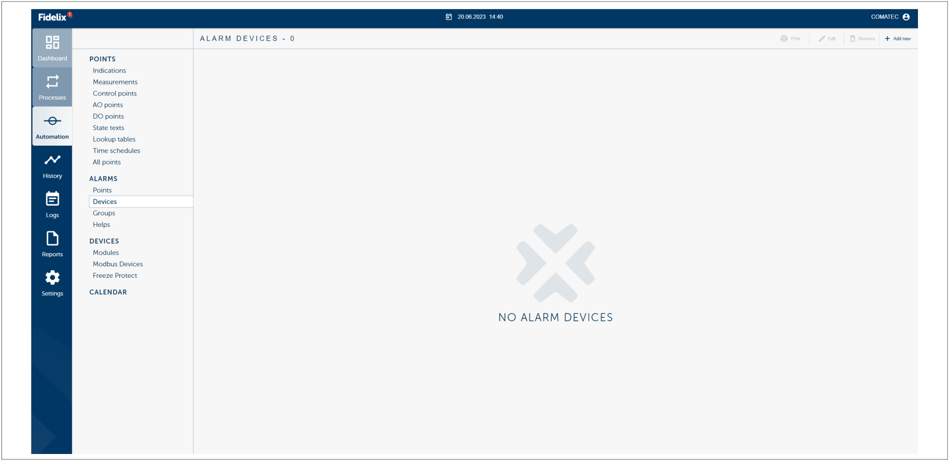
Note
Some users have no rights to acknowledged all alarms.
Points
Point type ‘Alarm’ can be used for:
- Supervising state of contact in DI module
- Displaying state controlled by IEC program
- Displaying value controlled manually
Devices
Devices which are used for alarm forwarding. For example email or sms.
Groups
Alarm devices and alarms points are connected to the alarm group.
Devices
Devices tab contains settings for the devices connected to the system. For example modules, modbus and ice protection system/freexze points.
Calendar
In the calendar view the user can:
- Add scheduled events (for example to the ventilation on the weekend or feast day).
- Check the coming events.
- List the coming events.
- Change the coming events.
The calender can be scheduled for 12 months and annually repeated events are possible.
Time scheduled events are available for:
- week (days from monday to sunday)
- E1, E2 and E3(special days)
- L1 and L2 (holiday) (EN LÖYTÄNYT NÄITÄ KALENTERISTA, VAIN E-ALKUISET LÖYTYVÄT)
Colours on the calender:
- Light yellow box - the ongoing day
- Dark blue box - Event on the calender
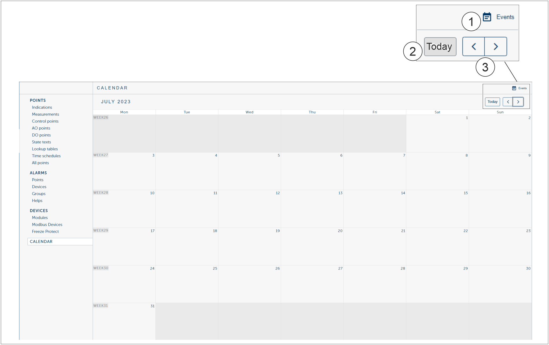
|
1 |
Events button. List of all events in the calendar is shown. |
|
2 |
Today button. The ongoing day is shown on the calender. |
|
3 |
Back and Forward buttons. Go back and forward months in the calender. |
History
On the History tab the user can have longer period point infomation instead of 12 points. The information is minutes, hours, days and months.
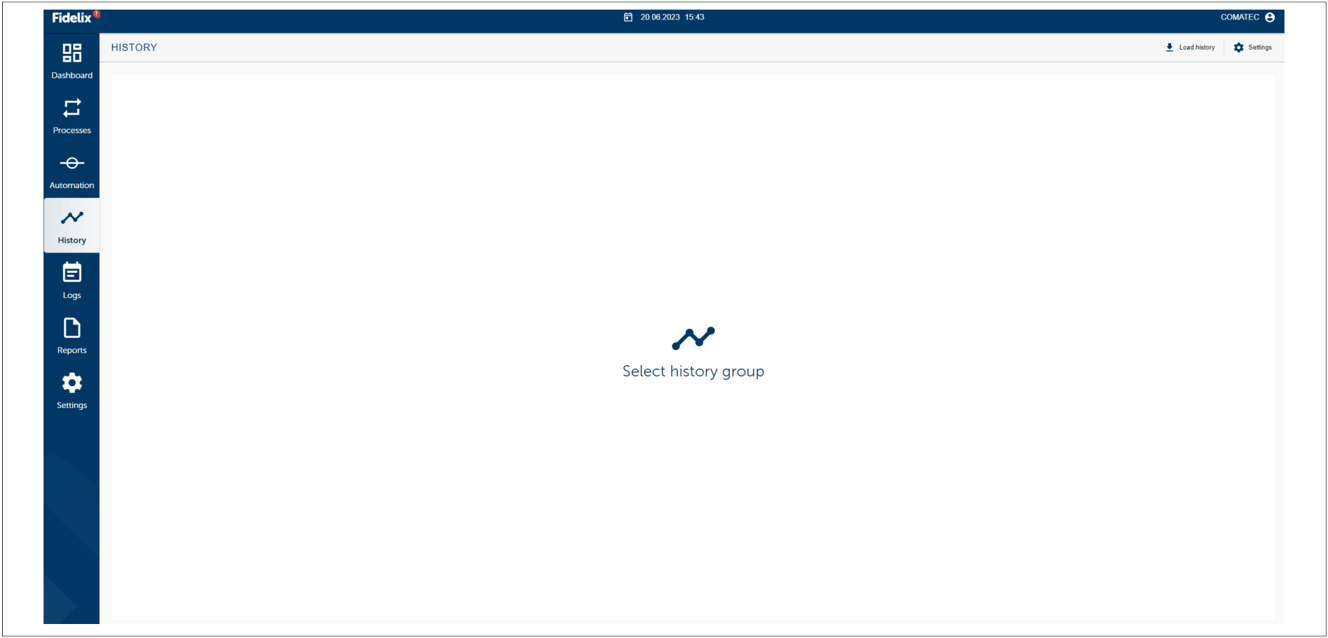
Logs
In the event log the user can find information events, alarms and debug. The user can see who has logged in and out and also the point changes. Information can be sorted by the:
- Point changes
- Events
- Loggins
- Debug
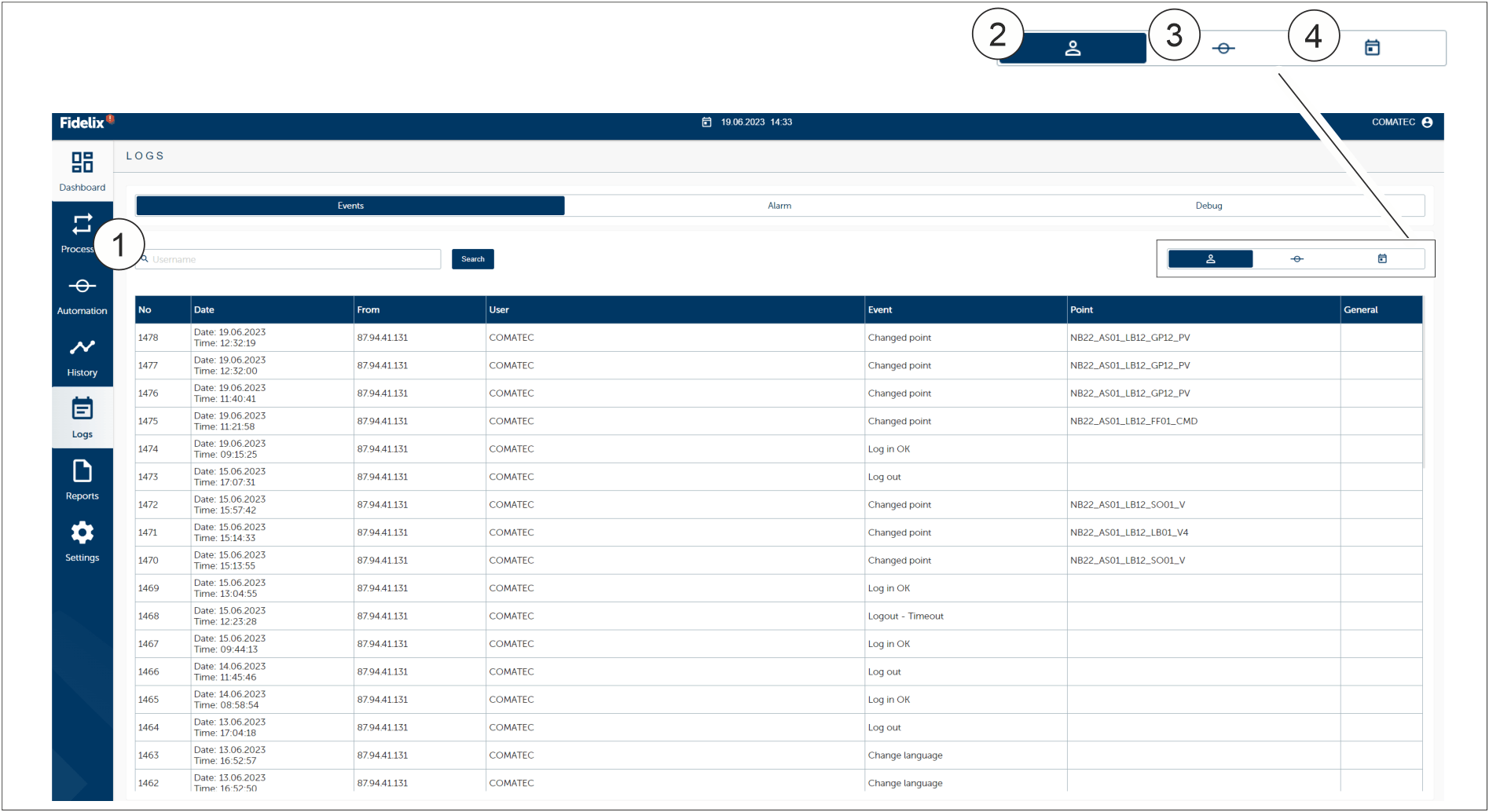
|
1 |
Search field |
|
2 |
Username |
|
3 |
Point |
|
4 |
Time span |
Reports
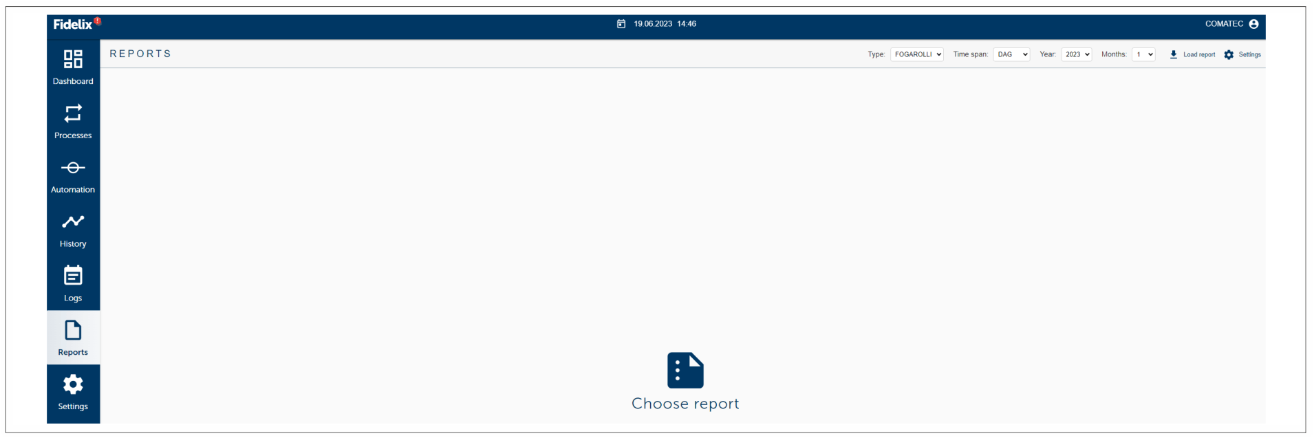
On the Reports tab the user will see for example water and energy consumption. The user can not modified reports.
Settings
On the Settings tab the user can see
- Dashboard
- System settings
- Network settings
- User settings
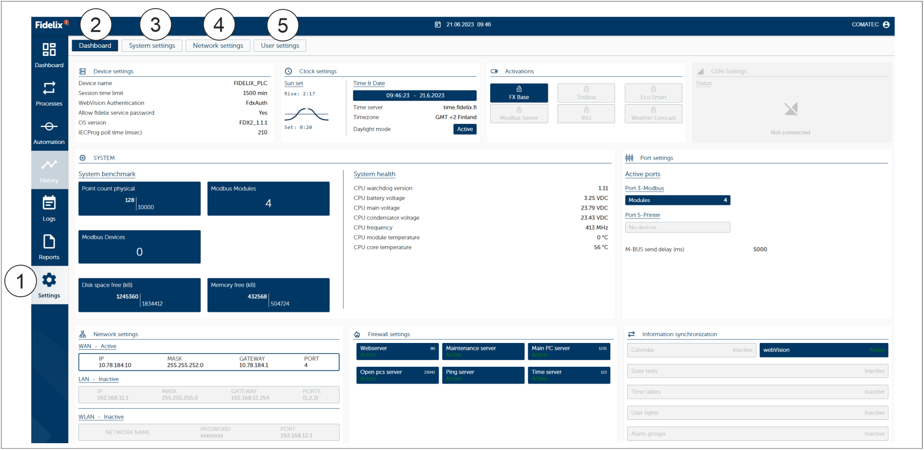
|
1 |
Settings |
|
2 |
Dashboard |
|
3 |
System settings |
|
4 |
Network settings |
|
5 |
User settings |
Dashboard
Dashboard tab is for general settings, general diagnostic and for quick overviews.
System settings
Settings concerning system.
Network settings
Settings concerning network.
User settings
Settings concerning user.
Logging in and outLogging in
Note
The system time default is 15 minutes. If the system is unoccupied over 15 minutes the system will log out the user for the safety reasons. If the view is dim or on the screen saver tap the screen to activate it. The default time can be changed on the Settings.
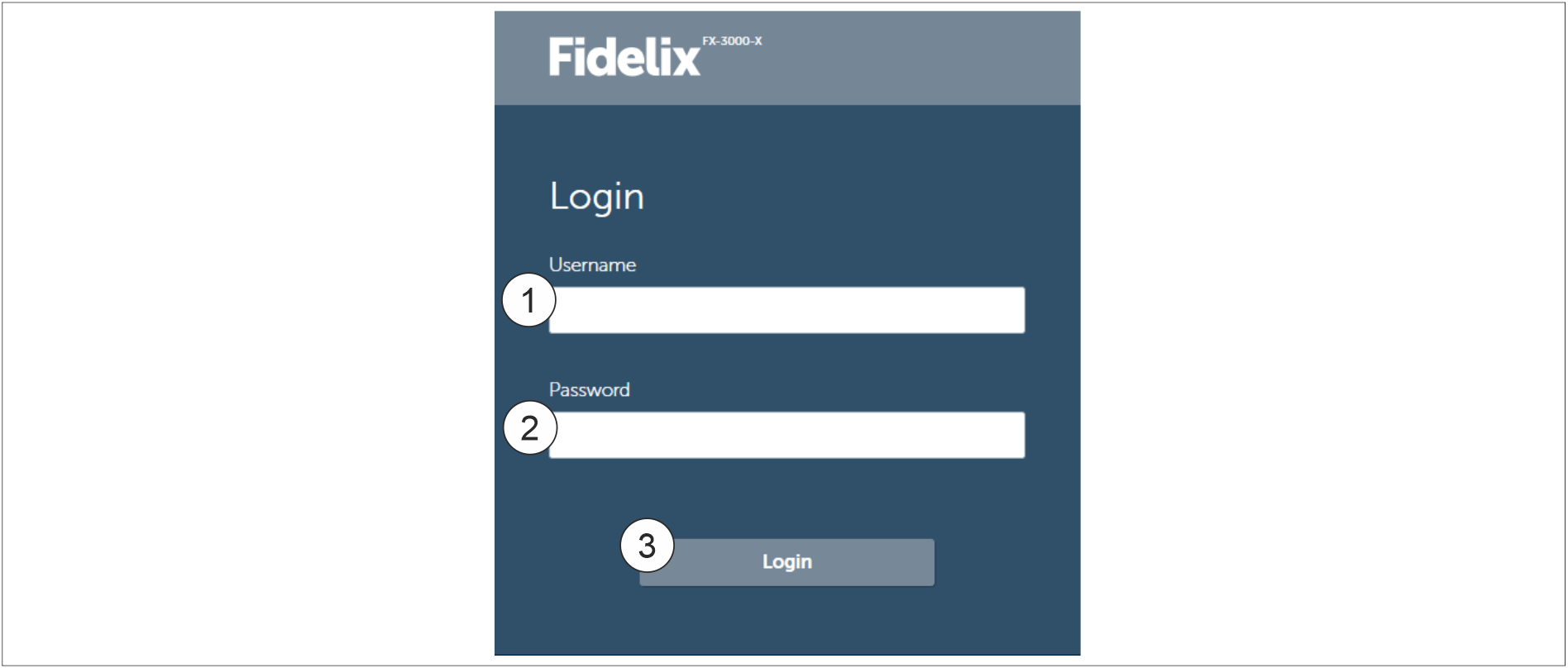
|
1 |
Username |
|
2 |
Password |
|
3 |
Login |
- Tap the Username (1)
- Enter the username with the pop-up keyboard.
- Tap the Password (2)
- Enter the password with the pop-up keyboard.
- Tap the Login (3) button to log in. The Front page of the system opens.
Logging out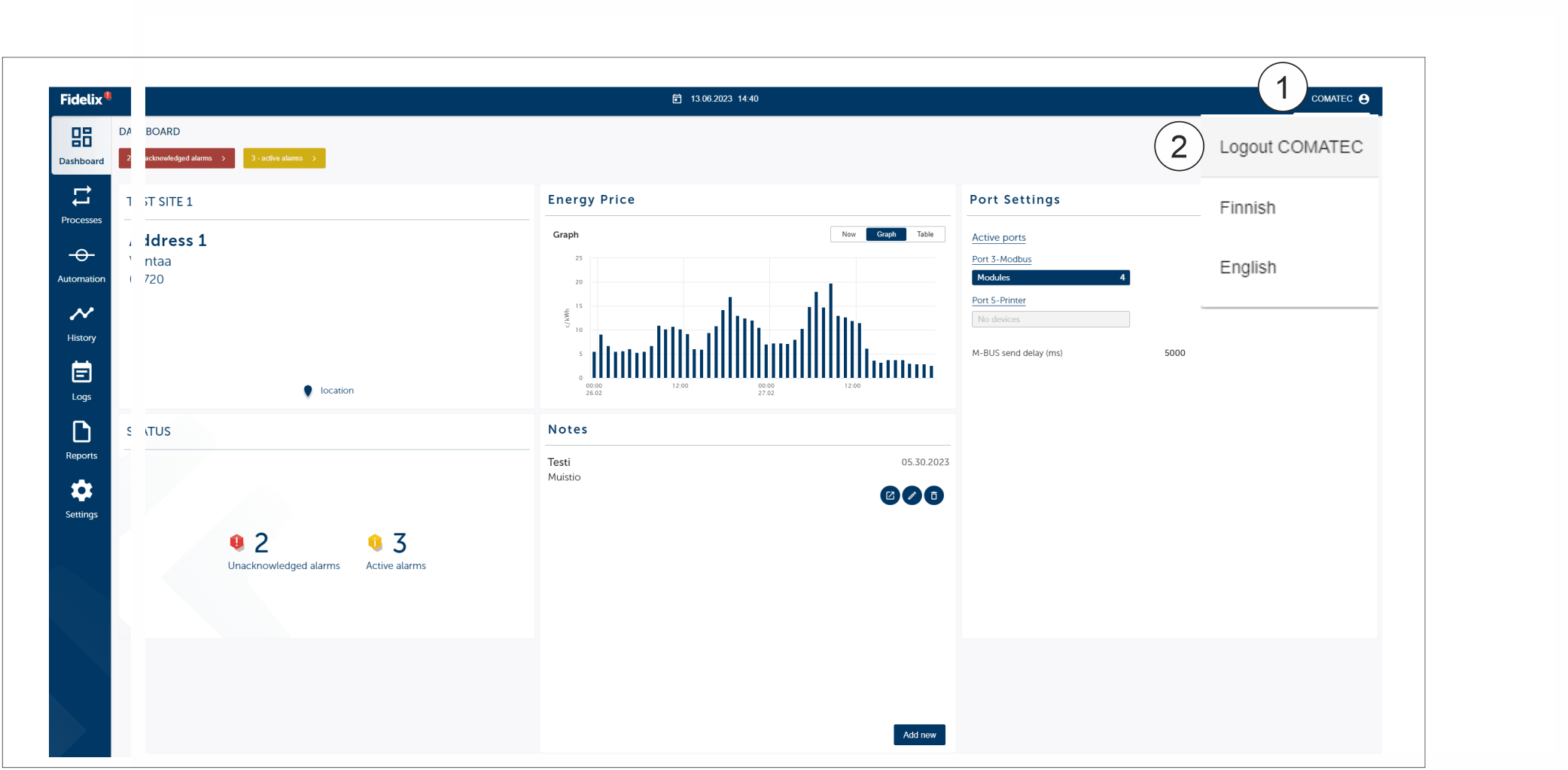
|
1 |
Log out and language settings |
|
2 |
Logout |
- Tap the Log out and language settings (1) button.
- Tap the Logout (2) button.
System language
Changing system language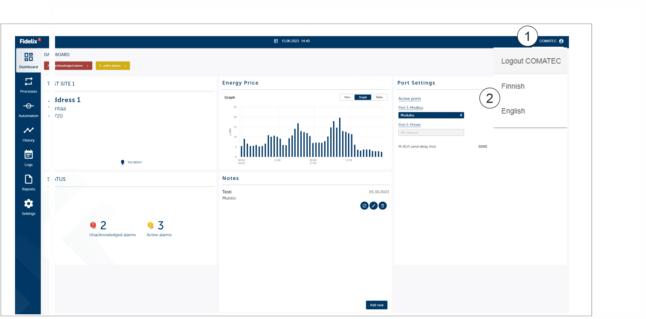
|
1 |
Username button |
|
2 |
Language button (Finnish, English) |
- Tap the Username (1) button on the Dashboard.
- Tap the Finnish or **English**(2) button.
Note
Changing the language will change the system language not the process picture language.