First open FX-connection from FX-editor.
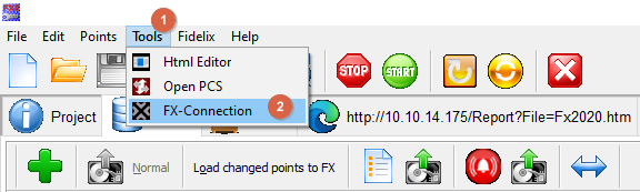
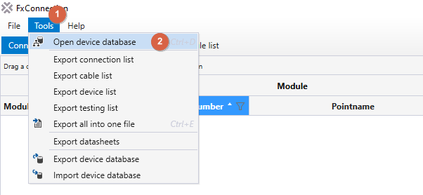
Then from FX-connection open "Tools" menu and choose the option "Open device database".
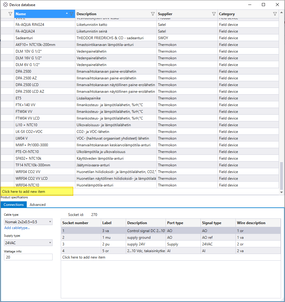
The list that opens, shows all of the devices currently added in to FX-connection. To add a new device scroll to the bottom of the list and click on "Click here to add new item" button.
When you click this a new row will be created.

Type the name of the device and a description for the device and press enter key on your keyboard.

Now find the new device in the list of devices and click on it.
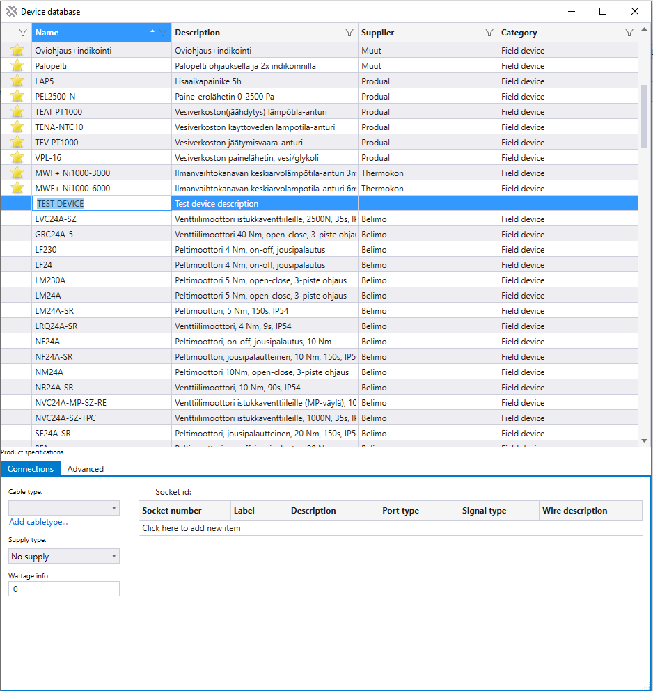
Now you can start giving the device specifications.
In the bottom of the list is the "Product specifications" window.
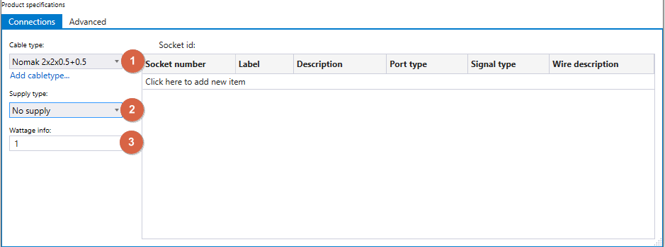
- Choose the default cable to be used with the device.
- Choose supply voltage if needed for the device.
- Input optional wattage info for the device if known.
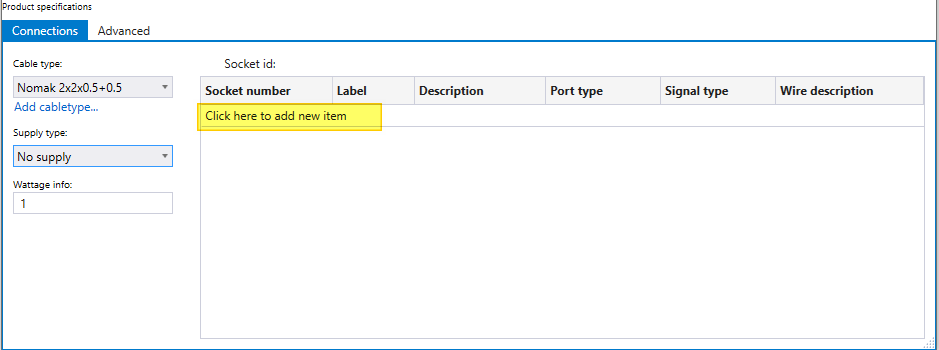
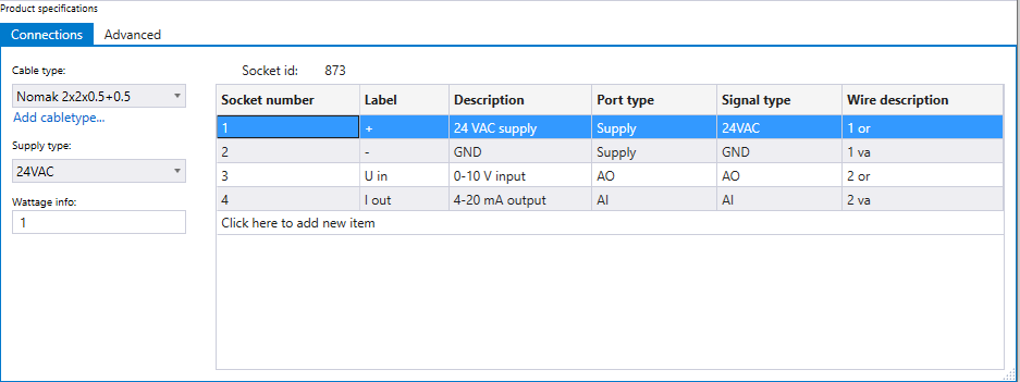
Then you need to add sockets to the device. These sockets will show on the generated connection list and also determine the wire numbers/colors to be used for each connection point.
Click on the "Click here to add new item" button.
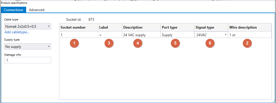
Now you need to choose the number for the socket. For example in Nomak 2x2x0.5+0.5 cable the sockets 1-4 refer to wires: 1 orange, 1 white, 2 orange, 2 white.
- Choose the socket number for the row selected
- Wire description is automatically added according to chosen cable type and socket number
- Write a label for the socket. This should be the label on the connection point of the device
- Write a description for the socket, for example 24 VAC, GND, 0-10 V out...
- Choose Port type. For supply voltage and ground choose "Supply", for input and output sockets choose the type of point that the point will be connected to in CPU. So for example a sensors measurement signal will have the port type "AI".
- Choose Signal type. This is dependent on port type, for supply type choose the volgate used or GND for ground sockets, for input and output types choose the connector in IO-module to be used for that socket. So for example a sensors measurement signal will have the signal connected to "AI" point if a IO-module.
Press the enter key on your keyboard to add the next row and repeat previous steps. Add all the connection points as sockets that you need to use from the device.
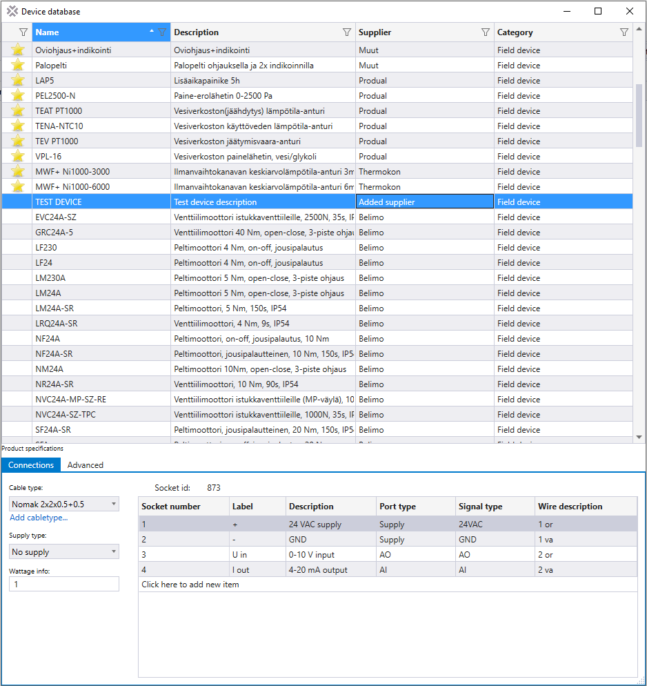
Example below, of a device that has a 24 VAC supply voltage, 0-10 V control input and 4-20 mA measurement output.
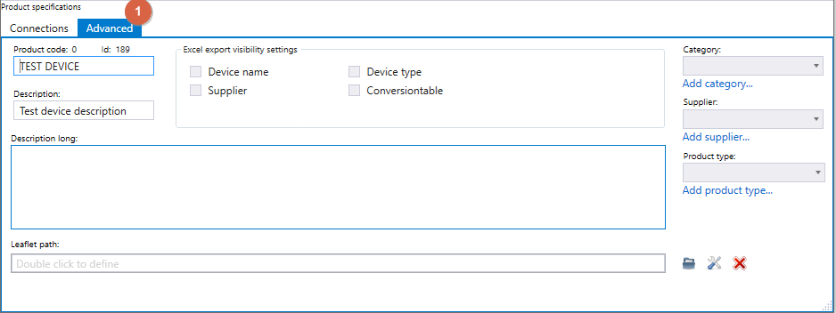
Then click on "Advanced" menu to add more details for the device.
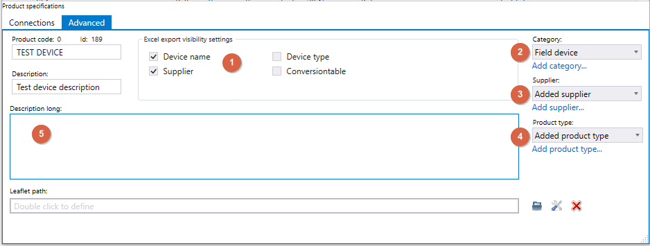
- Choose what information for the device will be visible in generated Excel files.
- Choose category. Is the device an internal component of the substation, a field device or some other type of device.
- Choose supplier/manufacturer of the device. If the manufacturer isn't on the list, you can add a supplier, by clicking on the "Add supplier..." text below the option field. This opens a dialog box, where you write the name of the supplier and an optional description for the supplier, then click the "Add" button.
- Choose product type that best describes the device. Product types can also be added the same way as suppliers.
- Write an optional description for the device.
The new device has now bee added to the database and can be used for points.